


CYPEPLUMBING Water Systems is a program created to assist the project designer with the design and analysis of water supply installations.
This application is integrated in the Open BIM workflow via the BIMserver.center platform.
Field of application
CYPEPLUMBING Water Systems carries out the analysis and design of all water supply installations or only those selected by users, for any type of building, in compliance with predefined standards, personalised design configurations of other standards, or personal technical configurations.
Country |
Standard |
|
CTE DB HS 4 |
|
NBR 5626 |
|
NTC 1500 |
|
NF DTU 60.11 |
|
UNI 9182 |
|
DR n.º 23/95 (RGSPPDADAR) |
|
BS 6700 |
|
IPC UPC |
|
EN 806-3 |
|
Configurable standards |
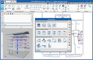
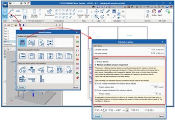
Program settings
The program allows users to define all the settings (drawing and calculation options, selection of materials and equipment, design options and checks to be carried out) that are required to introduce and design the installation in accordance with the standards described above. Additionally, users can personalise the program settings.
Analysis and drawing options
CYPEPLUMBING Water Systems carries out the hydraulic design using “Darcy and Weisbach” formulas, and applying the friction factor using the Colebrook and White formula.
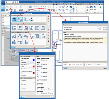
Users can define a general configuration for drawings. It is possible to choose the type of line to use for pipes in the installations, the colour of layers containing them, general symbols to be applied and references to be printed on floor plans.
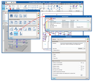
Material and equipment selection
The software contains catalogues of predefined equipment to develop the installation and allows users to introduce catalogues, which they themselves can configure.
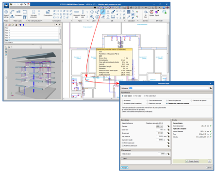
Design options and checks to be carried out
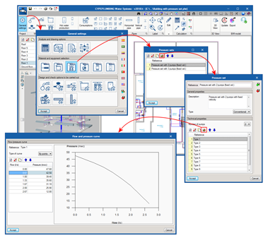
CYPEPLUMBING Water Systems also allows for the design and checks to be carried out to be configured for any element of the installation, supply connections, consumption points, deposits, pumping systems, and horizontal and vertical pipes.
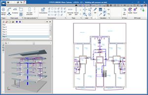
Workspace
The software is designed to carry out the design of the installation in a 2D workspace with the possibility to view, in real time, the 3D view of the installation that has been introduced.
The program allows for the design to be carried out on 2D templates from the BIM model using IFC format or DXF-DWG templates, DWF or images (.jpeg, .jpg, .bmp, .wmf).
It is also possible to work by layers, on the different networks the program allows users to design:
- Cold water network
- Hot water network
- Return water network
These layers can be managed in the 2D and 3D workspaces.
Calculations and checks
The program designs networks in accordance with the selected standard or personalised configuration to apply, and carries out the required checks.
The analysis of the tree of the installation is carried out by calculating gross and simultaneous quantities of flow, where the simultaneity can be configured.
It calculates and carries out a graphical representation of the worst and best case pipe spans of the installation.
CYPEPLUMBING Water Systems automatically designs the water supply installation or installations that have been introduced in the building. The program takes into account the checks that have been defined in the “Design and check options to be carried out” section. It can carry out a partial design of each installation element. Additionally, when designing the complete installation, CYPEPLUMBING Water Systems offers users the possibility to use iterative design processes by applying the personalised criteria that has been defined in “General Settings” > “Analysis and drawing” > “Calculation options” > “Minimum available pressure requirement”.
Using warnings, the program informs users of any non-conformity with the code or any installations that have been developed incorrectly, to aid them with the correct configuration.
The results can be viewed on the elements and also in the results reports that are generated by the program.
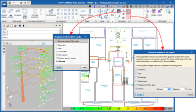
Graphical analysis of the results
CYPEPLUMBING Water Systems allows users to graphically analyse the results of the installation. Users can select the parameters that intervene in the hydraulic design of the installation that they wish to analyse, and the program draws the installation using a colour scale, for a quick and easy view of the results in the 2D and 3D views it provides on-screen.
It is possible to study specific result ranges in the global aspect of the installation.
Integration in the Open BIM workflow via BIMserver.center®
Using the BIMserver.center® platform, participants communicate directly with the applications that form part of a project integrated in the Open BIM workflow. This integration is achieved using IFC information interchange files with a previously defined BIM model:
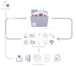
- BIM model import
This is carried out using IFC format files that have been generated by CAD/BIM programs such as IFC Builder. The program collects, as well as the building spaces, the positions in the three-dimensional view, of the fittings included in the IFC files.
- Export information on IFC files
CYPEPLUMBING Water Systems exports an IFC file with the position of the pipes in the three-dimensional model, so the other programs of the workflow can view them. This way, the BIM model is updated and the Open BIM workflow is consolidated.
- Synchronisation with the BIM model
Each time there is a modification in the BIM model, the program can incorporate the change in the project so users can work in parallel with other specialists of other disciplines.
Documents
The program generates the following documents:
- Results, checks and quantities reports
- Export of the quantities to BC3 format
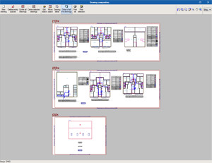
Drawings and diagrams
CYPEPLUMBING Water Systems generates floor plans with several configuration possibilities:
- Floor plans of the building (groups all the keys of the floor plans) or per plane.
- Floor plans with the possibility to manage the wastewater networks on different drawings.
It is possible to print and/or export the diagrams and drawing from the program to different formats (DXF, DWG, JPG, EMF, BMP).
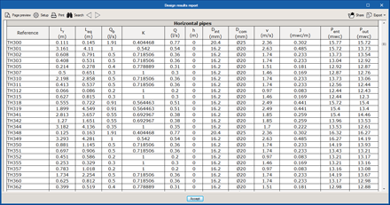
Results reports
The program generates reports containing the results obtained for the installations. The reports generated from the design of the installations can be printed out directly from the program or exported to several formats (TXT, HTML, RTF, DOCX, PDF).
The program generates the quantities report of the pipes and equipment. These quantities can be exported to FIEBDC-3 (BC3) format.
User license
To be able to work with CYPEPLUMBING Water Systems, users must have the corresponding permission to use the program, which is the same that provides access to the “Plumbing installations in buildings” module of CYPECAD MEP, if the user license is updated to the 2018.f or higher version.
Tel. USA (+1) 202 569 8902 // UK (+44) 20 3608 1448 // Spain (+34) 965 922 550 - Fax (+34) 965 124 950